By me
All photos (and videos) me too, copyrighted
Despite there being GA material aplenty in Croatia nowadays, for this next piece I decided once again to go for one of my “periodic airliner exceptions”. The reason this time was the opportunity to photograph an entire CFM International CFM56 engine in the nude, something so rare even for us airliner drivers that I simply could not leave it at “just another set of photos” somewhere on my hard drive.
Admittedly, the mass of bits and bobs that is a jet engine is somewhat underwhelming to look at on a computer screen, especially with no sense of scale; but even then, the sight is more than enough to send the geek-o-meter right off the scale. Working under the assumption that mine wouldn’t be the only one, I rolled up my sleeves and dialed up my carrier’s PR department for an amen to go to town in true Achtung, Skyhawk! style…

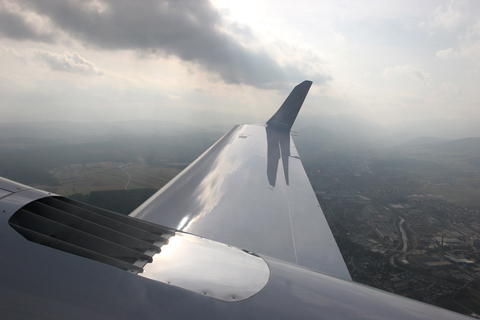
It’s far from the most exciting or advanced engine out there… but it still deserves some love for its reliability and longevity! Plus, it’s good for some cool shots – such as here, windmilling with a 30 knot breeze up its tailpipe
The Power Of Flight
Being such an ubiquitous engine, much has already been written about it – so, if no one objects, we’ll cut straight to the chase. The first bit we need to address is the name: C, F, M, 5 and 6. Even a brief search online will quickly reveal that this name is actually a portmanteau of General Electric’s CF6 (Commercial Fan 6) and Snecma’s M56 (Moteur 56). The “problem” here is that this is a bit misleading, since it implies that the CFM56 is a mashup of bits from these two engines. This doesn’t quite work since a) the CF6 is a big brute of an engine that develops 240 kN of thrust (twice that of the most common CFM56)… and b) the M56 never really existed in the real world. Intended to be Snecma’s stab at the 90 kN thrust range, the M56 was still a paper project by the time the CFM International joint venture was announced, with barely the essential tech and concepts worked out.
To make it slightly more complicated, GE’s contribution to the CFM56 is actually based on the F101, a reheated high-performance military engine developed for the original supersonic B-1A Lancer. Use of the CF6 designation came in handy purely out of convenience, since GE and Snecma had already collaborated previously on European production of parts the CF6-50 powering the A300 and A310.
The 50-50 division of work established within CFMI thus sees GE contribute a modified version of the F101’s high pressure section (the high pressure compressor, high pressure turbine and the entire combustion chamber), while Safran (today’s Snecma) supplies the fan, low pressure compressor, low pressure turbine, accessory gearbox and exhaust section, all of which were developed for the stillborn M56.
The specific engine I had the opportunity to photograph is called the CFM56-5B4 SAC, a typical engineering sausage that immediately tells you pretty much all you need to know:
- 5: developed for use on the Airbus A320 Family1
- B: an upgrade of the “first gen” 5A with a modified fan and low pressure compressor
- 4: developing 120.1 kN for take off and 108.4 continuously
- SAC: variant featuring the Single Annular Combustor2
1 while it’s easy to assume that “a CFM56 is a CFM56”, quite a lot of engineering has to go into making the engine suitable for use on other airframes. Perhaps the best examples are the -3 and -7 variants developed for the 737-300/400/500 and 600/700/800 respectively, whose gearboxes had to be repositioned and fans made shorted to make them fit under the type’s low wing with reasonable ground clearance (other changes on the -7 include just 24 fan blades versus the 36 on the -5, and a redesigned core to compensate for the fan’s reduced efficiency)
2 normally not part of its formal designation, the combustor type does have some bearing on the engine’s performance. In the modern turbofan, the combustion chamber is a doughnut-shaped cavity in the middle of the engine in which fuel is mixed with air and turned into noise. Fitted at the front of this chamber is the combustor, in essence a ring mount for 20 fuel injectors that spray atomized fuel into the chamber. In SAC engines, there is only one set of injectors; in 1995 however, CFMI started offering the Dual Annular Combustor (DAC) option, which featured – obviously – two sets of injectors. The first – called the Pilot Dome – is optimized for lower power settings, while the second one – called the Main Dome – is optimized for high power settings. The Pilot Dome operates in all stages of flight; however, when extra oomph is required (such as during take off or climbout), the Main Dome comes online to increase efficiency and better use the energy in the fuel. While there are some fuel consumption benefits to this setup, the main party piece is better throttle response – and a significant reduction in NOx emissions, reported to be 40-45% over SAC models

While it may not be as exciting to look at as the fancy GenX or P&W’s Geared Turbofans, the 56 nevertheless has a simple elegance and eye-pleasing symmetry
Other details? Well, despite being a sizable lump of machinery – 2.6 m long, 1.9 m wide and 2.1 m tall – it tips the scales at just 2,382 kg dry (without oil & hydraulics loaded), and 2,420 kg wet, i.e. fully loaded and ready for installation into the nacelle.
Since I believe that continuing to solely talk numbers would defeat the (hopefully) educational point of this article, it’s high time to get down to the best bits: the photos! 😀 Alas and unfortunately, some of them will not be up to my usual standard; the aircraft that I got to inspect – a pretty stock A319-112 – was undergoing deep maintenance at the time, parked in a hangar with a scorching sunlit day outside. Thus, the situation was one of extreme backlight and unfavorable contrast, which took quite a deal of both physical and electronic work to compensate for (not to mention a ton of sweat). Hopefully though, the sight of all those purposeful do-dads and thingamajigs will make up for it!
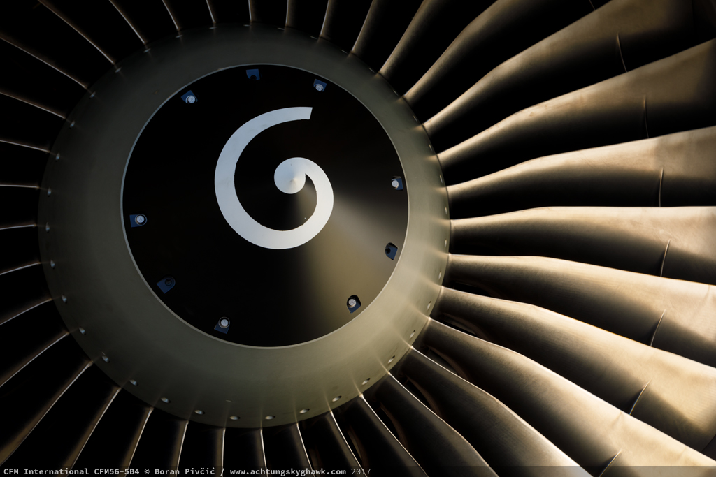
The golden engine. To stop it from turning red, its aforementioned 120 kN take-off power is limited to 5 minutes normally – and up to 10 minutes in case of an engine failure. Of interest, the three empty slots around the spinner are not missing bolts; they are in fact slots for tools necessary to remove the spinner and access the fan’s inner assembly

Despite being a “middle-of-the-road” engine with a thrust rating of “yawn”, the CFM56 nevertheless looks pretty brutish once you take its clothes off. It’s aggressive wasp-like lines nicely highlight its main bits; from the front, there’s the big fan – the compressor section (with the smallest diameter) – the fat combustion section at the rear – and finally the turbine & exhaust section. Like many other turbofan engines, the CFM56 is a two spool design: it has an inner shaft with a High Pressure (HP) turbine driving the HP compressor – and an outer concentric shaft with a Low Pressure (LP) turbine driving the LP compressor and fan. The compressor section itself sports four LP and nine HP stages; while the turbine section has a single HP stage and four LP stages. Also, this particular engine is missing its tail cone, which is nearby undergoing some servicing

One of the first things that catches the eye is the size difference between the fan and the core – and consequently, the difference in the mass of air that flows around the core vs the mass that actually goes through it. Called the bypass ratio, on the 5B it is 1:5.7 – meaning that the mass of air flowing through the bypass duct (visible to the right) is 5.7 times greater than the mass of air actually entering the core (and participating in the whole combustion thing). The manuals say that the total mass flow (exhaust + bypass) is 407 kg/s at take off power; to give a fun but completely useless reference, this means that both engines would need slightly under five and a half hours to suck all the air out of Boeing’s Everett production line (by volume the largest building in the world)

Another detail that does not escape notice is the mass of machinery hanging from the fan case; called the accessory gearbox, it turns the rotation of the HP spool into power for a wide variety of essential services, including the oil pump, main fuel pump (there’s also an electrical backup), engine-driven hydraulic pump (w/ electrical backups as well), AC generator and the FADEC (the engine’s electronic brain). It also mounts the pneumatic air starter, which uses high pressure air from the APU or an external source to spin the HP spool up for start (electrical starters are not used on engines of this size, since the size of the starter – not to mention the current draw – necessary to bring the HP spool up to the required speed for start would be highly impractical). Of interest, this gearbox was one of the main “trouble areas” when the CFM56 needed to be lodged underneath the lowrider 737…

A nice plan view of the backside of the CFM56 – which required quite a lot of maneuvering, sweating and swearing! One of the most difficult parts of the engine to design, the HP and LP turbines have to operate in some properly difficult conditions; the HP turbine is in a particularly tough spot, being subjected to exhaust gases that measure up to 950°C on take off (and 915 continuously). To survive this torture for thousands of hours on end, each turbine blade has an elaborate cooling system that ducts air from the pneumatic system THROUGH the blade itself, and then expels it overboard through dozens of tiny pores on the blade surface – thus both cooling the blade from the inside and forming a thin protective film along it on the outside. And just to drive home the point of “hard to design”: there are a total of 650 blades in the HP and LP turbine… despite these tricks though, the blades still suffer from a fascinating phenomenon called blade creep, in which the combination of heat and high angular speeds minutely deform and stretch the blade in span, shifting its mass towards the tips; the good news is that this can actually be used to good effect, since by modulating the flow of cooling air, the blade span can be somewhat regulated and thus the gap between the tip of the blade and the compressor casing can be controlled to achieve the best possible efficiency (called the Turbine Clearance Control (TCC) system)
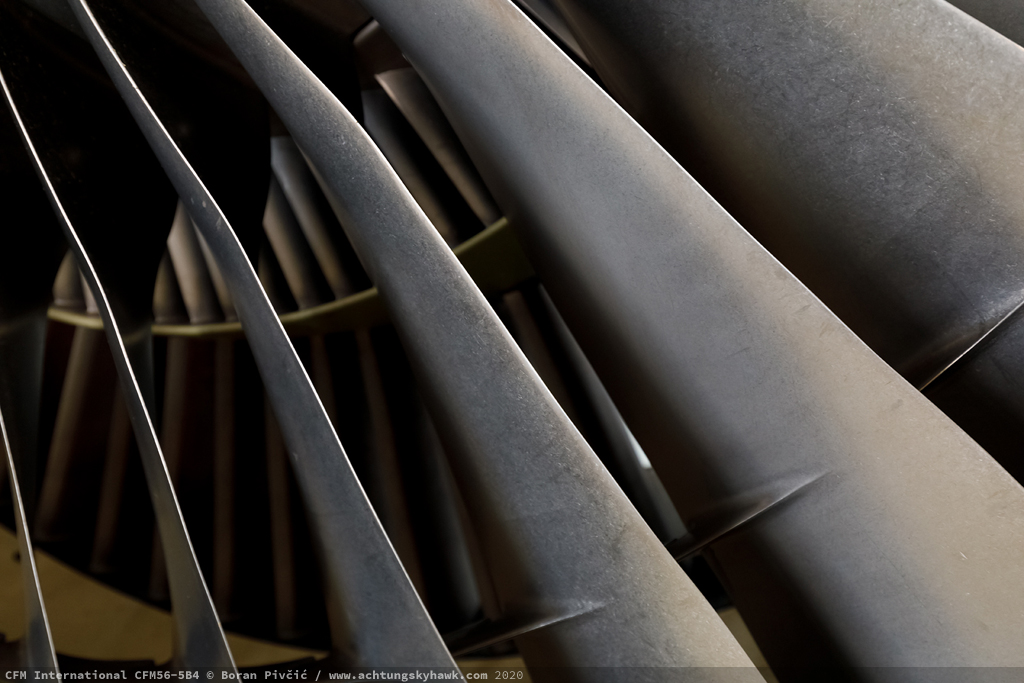
Fan art. The largest single moving part in the entire engine, the fan measures 1.73 m in diameter and sports – as mentioned earlier – 36 blades. Despite its speeddy looks though, it (and the entire LP spool) revs at a relatively sedate maximum of 5,200 RPM (clockwise when viewed from the back), just slightly faster than the redline of a typical automotive Diesel engine. The HP spool is a bit sportier, revving up to as much as 18,513 RPM; sounds impressive, but it actually perfectly illustrates the physical reality of “the bigger they are, the slower they spin”. For comparison, in the much smaller PW150A out of the Q400, the LP and HP spools spin at 27,000 and 31,150 RPM respectively at max power… while the Q’s “screaming demon” Hamilton Sundstrand APS 1000 APU goes all the way up to 64,154 – fast enough to make itself clearly heard even above the din of the typical airport…
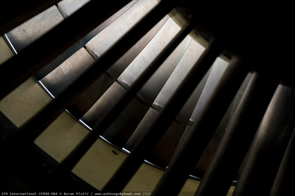
An “upskirt” peek at the fan from the other side reveals yet more fascinating details. In essence, all of the blades on the fan, compressors and turbines are installed at one preset angle – just like the fixed pitch propellers on light aircraft. This means that the blades are only really efficient at a few combinations of forward speed and RPM; change either, and efficiency begins to drop off. Since it is ruinously expensive (and mechanically quite complicated) to make the blades themselves adjustable, jet engines are fitted with stator vanes (visible in the foreground) that stabilize and direct the airflow onto the next compressor/turbine stage, thereby preventing eddies that could result in inefficient and unstable engine operation. The vanes come in static and variable flavors, the latter adjusting their pitch to suit the prevailing conditions (just like the constant speed propeller). Note also the protrusions on the fan blades (visible in the previous shot as well); these are called shrouds and are used to give the blade additional rigidity, reduce vibration and alleviate some of the loads on the blade’s inner structure. Predominantly a feature of “old school” engines with titanium blades, they are unnecessary on modern composite fans, since the latter are lighter, far more rigid, and can be shaped more precisely to reduce aerodynamic loads
Another interesting “feature” of shrouds is the noise they make when the engine is windmilling – captured (rather loudly!) in the video below. In essence, the blades of the fan, compressors and turbines are not rigidly fixed to their associated shaft, but are free to move about longitudinally in their mounts. In normal operation and at normal rotation speeds, they set themselves into one position and stay there; but when windmilling (or turning at lower speeds), they jiggle up and down making a racket. Among several benefits, the main point of this freedom of motion is to absorb and dampen the shaft’s vibration, and prevent some of that energy from being transferred to the blades themselves – energy that can cause internal cracks and various fatigue damage, stuff that is very problematic and very hard to detect (and had brought down more than one airliner in the past).
Shrouds add their bit by turning the volume up to 11, since during windmilling they tend to clap loudly against the next blade in line with every rotation. One needs to look no further than a comparison with the -7 series on the 737NG (below): its smaller fan does not need shrouds at all, since its shorter and lighter blades can be dampened just as effectively already at their root (just like compressor and turbine blades). Positive peace & quiet compared to the -5!

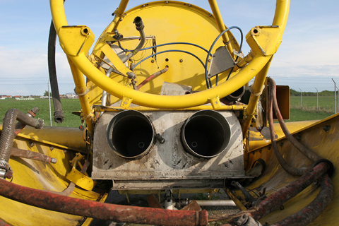
An abstract look down the bypass duct. The main features here are two of the four reverser blocker doors (visible right side), which open into the cold stream (the air flowing through the duct) and deflect a portion of it overboard and forward against the direction of motion to provide braking; note that the hot stream (the gases from the core) are not used for this purpose. Like all reverser systems, the one fitted to the CFM56 has a minimum use speed – 70 knots – below which there is a distinct possibility of the engine drawing in the highly turbulent reversed air, as well as ingesting foreign objects from the runway

And finally, some love for all the other bits of the engine that make it work in the real world: the fuel, electrical, oil, hydraulic and air lines, as well as various mechanical regulators, coolers, mounting points and whatnot. Dominant in view on the right are air ducts for the bleed air system, which bleeds air from several points along the HP compressor (the front and middle stages) to pressurize and air condition the cabin. Tucked in to the left-low of the T junction is the air starter valve, which ducts high pressure air from the bleed system to the air starter mentioned several photos earlier
Sources:
- Airbus – A319/320 Flight Crew Operating Manual (FCOM)
- CFM International – 20 years of CFM press release & CFM56 DAC press release
- EASA – CFM56-5B Type Certificate Data Sheet (TCDS) (PDF)
- General Electric – CFM56 brief history
- various CFM56 maintenance manuals + bothering the people who fix them for a living (they know who they are!)


")